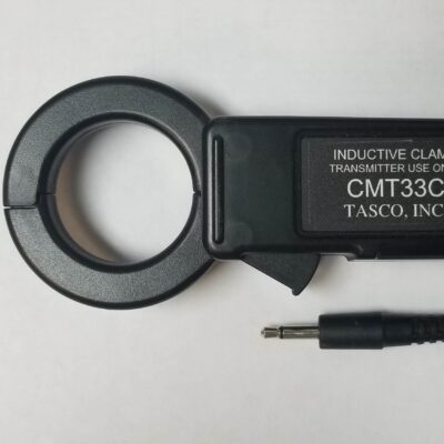
The Tasco Circuit Mapper System is a branch circuit identifier that allows the user to map branch circuits quickly and easily. The system is easy to use and will quickly pay for itself by saving labor time. The Tasco Circuit Mapper System is a revolutionary new branch circuit identifier. It uses new technology to map branch circuits with just one transmitter and one or more receivers. Instead of connecting at a branch circuit’s end point, the Circuit Mapper transmitter connects to the branch circuits with inductive (CT) clamps at the breaker panel. No direct electrical contact to the wire of the branch circuit is necessary. The receiver displays the corresponding circuit number when the probe comes in contact with the branch circuit outlet or light switch. Its simplicity of operation significantly reduces labor costs.
How it Works
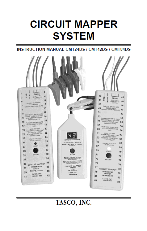
Click to Access our Circuit Mapper Product Manual
How to Use
The Circuit Mapper System Instruction Manual provides complete operating instructions. It should be read before operating the Circuit Mapper System, paying particular attention to vital safety information. Here is an overview of its operation:
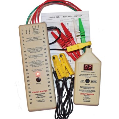
- Install a 9 volt-alkaline battery in the transmitter and receiver. Push and release the transmitter’s on/off button. A red LED will illuminate when the unit is powered up. Plug a yellow CT clamp lead into output jack #1 on the transmitter face. Clamps are interchangeable. You can connect a clamp to any output jack, and you can use any combination of output jacks simultaneously.
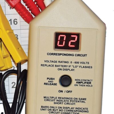
- Push and release the receiver’s on/off button. Insert the metal receiver pin through the opening on the yellow clamp. Note that the clamp must be completely closed. The receiver will show “01” to indicate that both units are ready to use.
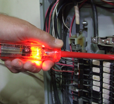
- Remove the panel cover in a manner such that no breakers are accidentally turned off. A magnet is built into the back of the transmitter. Use this to stick the transmitter to the outside of the panel in a convenient location. Attach the white alligator clip to the incoming neutral conductor or lug in the panel. Make a ground connection with the green alligator clip. Attach a red alligator clip to each phase HOT connection. You’ll need just two red alligator clips for single-phase/split phase panels and all three red alligator clips for phases A, B and C of 3 phase panels. Connect a yellow CT clamp to each branch circuit you want to trace. Plug the clamp leads into the transmitter and turn it on.
- Once connected via its clamps, the transmitter sends signals to both powered and unpowered systems. If working on an unpowered system, turn off the main breaker or fuse and leave the branch circuit breakers or fuses in the “on” position. Always connect the “PHASE”, “NEUT” and “GND” alligator clips from the transmitter to the corresponding lugs in the breaker panel when connecting the transmitter. Otherwise, it is possible to get multiple readings due to the transmitter signal coupling to the incorrect circuit.
- It’s a snap to operate the receiver. Turn the receiver on. The metal prong should contact the conductor or the wire being tested. For outlets it is not necessary to remove the cover plate, simply put the probe into the HOT side of the outlet. For switches, remove the cover plate and touch the probe to the always HOT screw terminal being careful not to short the probe to any metal boxes. Hold it there for at least two seconds. The readout will show the corresponding clamp number at the transmitter. If it is not possible to make direct contact with an outlet HOT conductor because both receptacles are in use, the receiver has a non-contact feature that is activated when the power button is pressed and held. Push and hold the on/off button while orienting the power cord under the nose of the receiver until a reading is shown. It may be necessary to rotate the power cord slightly so that the HOT conductor is closest to the receiver nose. Hold the button for another two seconds to verify a reading.
- For faster mapping on large job sites or with multiple panels, the CMT84DS can be used with up to 84 branch circuits simultaneously. It is also possible to use multiple receivers, purchased separately, simultaneously. For instance, multiple receivers can be used on the same floor of a large layout building or on separate floors of the same building.
For additional insights into the Circuit Mapper System’s operations and how to use it, check out the Circuit Mapper product manual.